Three Pathways for Kidney Stone Formation
 All kidney stones share similar presenting symptoms, and urine supersaturation with respect to the mineral phase of the stone is essential for stone formation. These clinical similarities have made it difficult for researchers to development treatments plans to successfully arrest stone formation for a specific stone former. However, recent studies using papillary biopsies of stone formers provide a view of the histology of renal crystal deposition which suggests that the early sequence of events leading to stone formation differs greatly depending on the type of stone and on the urine chemistry leading to supersaturation. Three general pathways for kidney stone formation (Figure 1) are seen: 1) stones fixed to the surface of a renal papilla at sites of interstitial apatite plaque (termed Randall’s plaque) as seen in idiopathic calcium oxalate stone formers (ICSF), 2) stones attached to plugs protruding from the openings of ducts of Bellini as seen in primary hyperoxaluria, primary hyperparathyroidism, ileostomy, small bowel resection, cystinuria, brushite, apatite, and distal tubular acidosis; and 3) stones forming in free solution in the renal collecting system as occurs in cystinuria. The presence of hydroxyapatite crystals in either the interstitial or tubule compartment (and sometimes both) of the renal medulla in stone formers is the rule, and has implications for the initial steps of stone formation and the potential for renal injury.
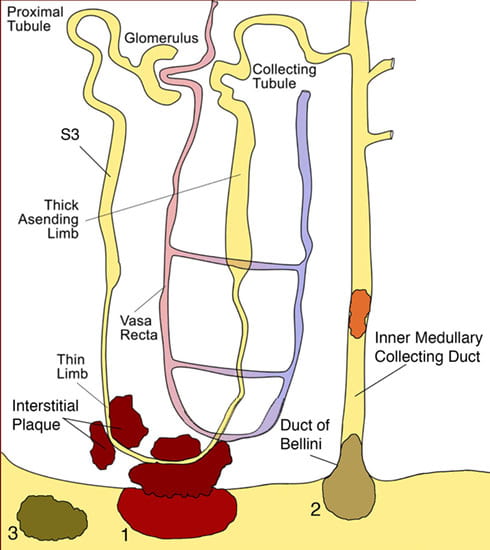
Figure 1.
Illustration of three pathways for kidney stone formation and growth. The first pathway (1) suggests that crystals in the urine can become attached to a site of exposed crystalline deposits of interstitial calcium phosphate following loss of the normal urothelial covering of the renal papilla. The second pathway (2) requires crystals nuclei to first form in the lumen of a nephron at sites of cell injury, which results in crystal attachment and growth that is called a intra-luminal plug. In this illustration, crystal attachment occurred near the opening of a Duct of Bellini and then a crystalline overgrowth grew on the end of the plug forming a stone that projects into a minor calyx. The third pathway (3) represents “free particle” formation in the collection system of the kidney. Published in: Evan AP, Pediatric Nephrology 25:831-841, 2010.
Interstitial (Randall’s) plaque:
The first pathway to be considered suggests that crystals in the urine can become attached to a site of exposed crystalline deposits of interstitial calcium phosphate (termed Randall’s plaque) following loss of the normal urothelial covering of the renal papilla (Figure 1). An anchored nidus of urinary crystals could form as an overgrowth on the interstitial plaque, permitting a fixed stone to form and potentially grow over many years. (Video 1; Removal of kidney stone from papillary tip). This theory is explicit in stating that sites of interstitial plaque are the initiating lesions.
It was the observations of Dr. Alexander Randall made from 1,154 pairs of post-mortem kidneys in the 1930’s that led to the theory that 1) attached stones are growing from and are supported by interstitial calcium plaque, 2) the sites of interstitial plaque can lose their urothelial cell covering allowing the plaque to be exposed to the calyceal urine and 3) that some detached stones have a concave surface with patches of phosphate material (possibly representing the attachment site to the interstitial plaque).
His first finding was an “innocent” appearing lesion. a cream-colored area near the papillary tip which appeared to be subsurface or subepithelial in location. This lesion was seen in about 20% of the kidneys he examined. By light microscopy, the lesion was found to be a plaque of calcium salts deposited in the interstitial tissue and definitely not intraluminal in location. Chemical analysis of the regions of plaque showed calcium, nitrogen, carbon dioxide, and phosphorous. His next major observation was finding a small stone (2 mm) that projected into the lumen of the renal pelvis. It was firmly attached to an area of visible calcium plaque and found to be composed of calcium phosphate. Such stones were found attached to papilla in 65 kidneys. A major flaw in Randall’s studies was a lack of detailed clinical data for each kidney stone patient he examined. Therefore, he suggested that all stones formed according to his hypothesis. This theory was easily challenged and his ideas fell out of favor. With the advent of digital endoscopes, our group realized that Randall had really discovered a critical factor in the formation of stones for idiopathic calcium oxalate stone formers, that being interstitial or Randall’s plaque. Calcium oxalate stones were determined to be attached to these sites of Randall’s plaque so frequently that this is the mechanism of stone formation in this patient group.
Interstitial Plaque Unique to Idiopathic Calcium Oxalate Stone Formers (ICSF)
Endoscopic and Histologic Observations
In the 1990’s our research team became interested in testing Randall’s theory of stone formation because of our fascinating surgical observations of renal papilla. To test the hypothesis that regions of Randall’s plaques develop in unique anatomical sites of the kidney and that their formation is conditioned by specific stone-forming pathophysiologies, we used state-of-the-art digital endoscopic equipment during percutaneous nephrolithotomy (PNL) for stone removal, biopsies were collected from such regions for histopathologic examination and a detailed clinical profile was developed for each stone former studied. ICSF patients were selected as the primary group of stone formers in that they appear to be a reasonably pure phenotype representing about 75% of all stone formers and do not have any systemic disease. Many but not all of these ICSF have idiopathic hypercalciuria (IH) a familial and presumably genetic trait. Digital images of all papilla were used to obtain papillary biopsies of regions with and without plaque for plaque surface determinations. During intraoperative endoscopy, sites of irregularly shaped regions of whitish material were observed on the papillary tip in varying amounts and usually surrounding the openings of the ducts of Bellini (Video clip 2; White plaque on papillary tip), the same plaque material described by Randall. The sites of interstitial plaque have been called white plaque and Randall’s plaque, these are terms for the same material. The plaque material is located deep in the urothelium (suburothelial) with a smooth outer surface except where it is pitted due to the removal of an attached stone.
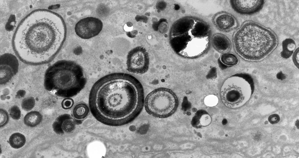
When a biopsy sample is removed from a site of interstitial plaque and viewed by light microscopy, minute spherical deposits of mineral are seen within the basement membrane of thin limbs of Henle in the inner medulla (Figure 2a-h). Initially, these mineral deposits are seen as electron dense spherically shaped objects of about 50 nm to multilayered spheres with alternating light (mineral layer) and dark (matrix layer) rings or bands (Figure 2c and e). All regions of crystalline material are encased in matrix layer (crystals are never naked). The individual deposits are then detected in the nearby interstitial space (Figure 2b) and appear to coalesce on the collagen bundles and become embedded in an electron dense matrix material generating islands of plaque that surround several tubular segments (Figure 2g). Whether these deposits originate in the basement membrane of thin loops of Henle and migrate into the interstitial space or nucleated directly on the collagen bundles is not known. These islands extend down to the basal side of the urothelium and encase the ducts of Bellini (Figure 2h).
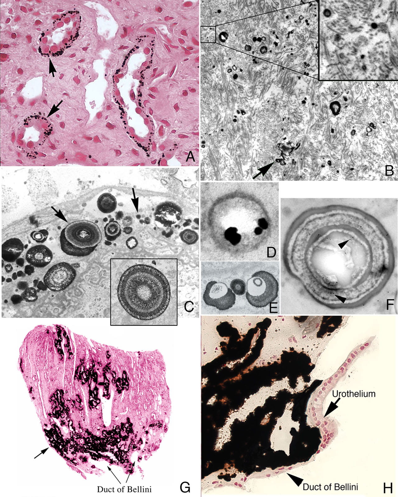
Figure 2
Histologic images of sites of interstitial (Randall’s) plaque in ICSF patient. Panels A-F show details of the initial sites and sizes of crystalline deposits in the inner medulla as seen by light (panel A) and transmission electron microscopy (panels B-F). Sites of individual, spherical deposits (panel A, arrows) are first noted in the basement membranes of the thin loops of Henle forming dense rings or bands around these tubules. The deposits are also seen in the interstitial space (panel B, arrow) and tightly associated with collagen bundles (panel B, insert). Ultrastructural analysis of the deposits reveals these structures to be spherical in shape (panel C, arrows) and with an internal morphology of alternating light to electron dense layers (1 to 9 layers) resembling a tree ring pattern (panel C, insert). Immuno-electron microscopic studies localized osteopontin (panel D, dark circles) to the interface of the electron dense organic layer and electron lucent crystalline layer while heavy chain 3 of the inter-alpha-trypsin molecule was localized to the organic layer (panel F, arrows). Individual deposits varied in size from 50 nm in diameter with a single layer to nine alternating layers (panels C and E). With time the individual deposits accumulate in the interstitial space embedded in matrix filling the interstitial space (panel G, arrow) all the way down to the basal surface of the urothelium (panel H).
Another technique to visualize regions of interstitial plaque is to image a renal biopsy by micro-CT. In regions of moderate plaque deposition, micro-CT reveals a collar or sleeve of material surrounding tubular segments (thin loops of Henle) of the inner medulla with an obvious empty tubular lumen (Figure 3a). In biopsies with denser regions of interstitial plaque, islands of material are seen completely surrounding the outer surface of individual tubular segments again exposing an empty tubular lumen (Figure 3b). No evidence of cell injury, inflammation, interstitial fibrosis or intra-tubular crystalline material was detected in any of the ICSF papillary biopsies.
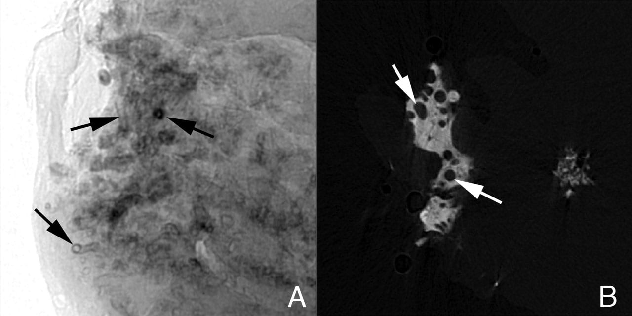
Figure 3
Sites of interstitial plaque in papillary biopsy of ICSF patient viewed by micro-CT. Panel A is a shadow image of a whole papillary biopsy sample. It reveals early sites of interstitial plaque deposits surrounding a number of nephron segments as a sleeve (see Figure 2, panel A, arrows). In this image the deposits are x-ray dense and appear black. Note that the tubular lumen is easily seen. Panel B is a slice from a tomogram that was generated from many shadow images of the biopsy. A large island of interstitial plaque (see Figure 2, panel G) is seen as a whitish material with dark circular profiles dotting it. The dark circles represent tubular segments passing through the interstitial plaque.
The mineral composition of the interstitial plaque was determined by micro-Fourier transform infrared microspectroscopy (micro-FTIR) to always be biological apatite (calcium phosphate), a mineral pattern similar to bone tissue (Figure 4).
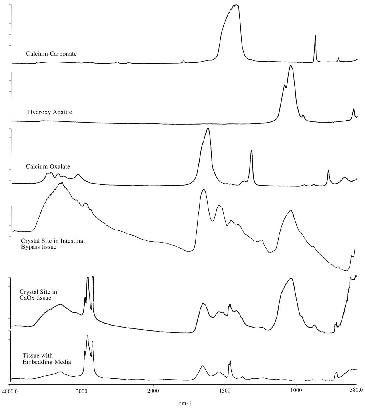
Figure 4
Fourier Transform Infrared Microspectroscopy (micro-FTIR) spectra of crystal deposits in an ICSF patient compared to a intestinal-bypass stone former. This figure illustrates a set of infrared spectra obtained for a group of standards (calcium carbonate, calcium oxalate, and hydroxyapatite), for a site of interstitial crystalline deposits in the tissue from the ICSF patient and an intra-luminal crystalline deposit for an intestinal-bypass patient, and for the tissue-embedding medium. The infrared spectra of the crystalline deposits for both patients show a spectral band for biological apatite, hydroxyapatite. Published in: Evan AP et al. J Clinical Investigation 111:607-616, 2003.
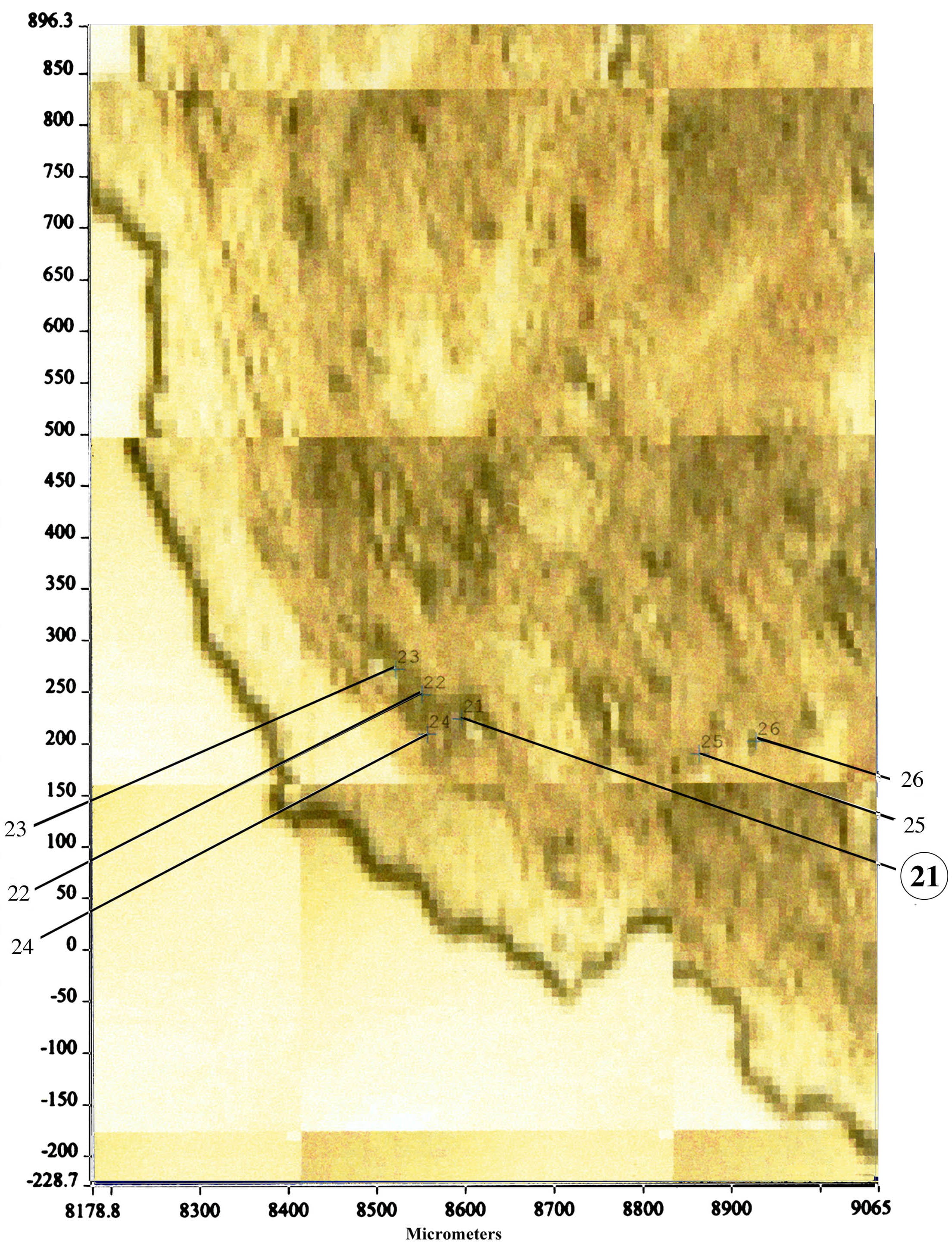
Randall had a better idea and labeled the interstitial mineral he discovered as calcium phosphate. Our group developed an entirely new method to determine the mineral composition in that interstitium space. We cut very thin sections of our papillary biopsies and mounted them on special slides in order to perform micro-FTIR analysis (Figure 5). We are able to detect mineral composition in a spot as small as 25 microns.
Hi,
Out of the 3 methods of stone formation shown here, which method of formation does uric acid stones adhere to? Do all stones that are attached to the kidney (not forming in free solution), have to start with a CaOx or CaP base?
Thanks
Josh
Hi Josh, Great question. Only one group has published on this and plugging seems one bet, free solution crystallization another. We have our own set of research data and have not as yet pulled it together for publication. But for uric acid, treatment is so stylized I hardly care: Raise the urine pH.